Showing posts with label accelerator pedal sensors. Show all posts

Wednesday, April 8, 2015

EPC NIGHTMARE

EPC WARNING LIGHT

Over the past 3 years I have had some  13775 EPC information requests. That's roughly 4500 request per year, each and everyone of  them EPC related.  I manages to help several Vag car owners with their EPC problems however many were unable to give me the  DTC codes that could be causing the EPC problems. So, If you have a scan of your car feel free to upload it to my blog, I will analyse it and post the answer for everyones benefit.  I have found that the commonest EPC problem is the accelerator pedal potentiometers. However they cannot be purchased as a separate item. You have to buy the complete accelerator pedal. There is a plug that is attached to  the accelerator pedal, the plastic bit where the yellow stickers are, contains the pots.  If you are having EPC problems you are not alone. Read some of your fellow Vag car owners woes.


NO EPC DTC CODES

What is EPC on a Volkswagen? My car loses power all the time. If  I turn the car off and leave it for a while,  the problem goes away. This happened to be a couple of months ago, and  I was forced to take  it to a VW dealer.  They had no idea what to do. The car idles  really badly and the EPC light is on from the moment I start it,  besides now the check engine light is also on. I'm  thinking about replacing the throttle body but it cost about is $600. That's crazy man.

TOO VAGUE & NO EPC DTC CODES

My EPC light came on and car lost all power, so now I am having the most weirdest problems. I got stuck on the freeway, my EPC light came on and I had to pull onto the shoulder of the road because I lost acceleration. Disconnected and reconnected the negative battery terminal to reset the system, then she was driving fine. Took it to VW guy but he has no idea what an EPC problem is or at least he wanted me to  pay him  first before would help. He wants $85 an hour.


NO EPC DTC CODES, CAN'T ASSIST

I have an  VW Polo 1.4 and the 'Check Engine light' and EPC warning light  blinks for the past few months. Replaced the throttle body and potentiometer  and wiring to the engine manifold were replaced.  The same problem still persists and car  will stall at random causing these warning lights and EPC to switch on.

NO EPC DTC CODES, NO HELP

My polo 1.2  epc light comes on when I stop at traffic lights and goes into limp mode then can only drive  15 mph max without   pressing the accelerator. Took  it to a service agents who condemned  the throttle body, so had it replaced. The EPC light still comes on.


Feel free to upload your VWSKODASEAT & AUDI scans.

Tuesday, October 21, 2014

EPC DEMYSTIFIED CONTINUED 2


Continued from EPC DEMYSTIFIED CONTINUED 1.


  ...  I only became aware of this when my EPC light went on due to the knock sensor. See picture blog.  More...


 PART 3


BREAKING THE CODE

What needs to be mentioned as a basis of understanding, is that OBD (on-Board Diagnostics) was introduced in the 70's along with CDI (capacitive discharge ignition systems) as DIY kits. Few cars had fuel injectors, points and coils were fast being taken over by electronic modules. During this time some standards were introduced but they were not very well defined and as such manufacturers developed their own and applied their specific systems and developed their own code descriptions which later became known as OBD1. This was considered undesirable and counterproductive since none franchised service, and general mechanical repair centers had to purchase different scan tools, interface cables and connectors, skills and manuals for each make and model of car they specialized in. This resulted in vehicle diagnostics becoming unwieldy expensive. In February of 1986, Robert Bosch founder of Bosch, introduced the CAN (Controller Area Network) serial bus system to  the Society of Automotive  Engineers (SAE) in motor town of Detroit.

This influenced the  Society of Automotive  Engineers (SAE) who subsequently drafted a list of standards and practices that aught to be implemented by all automobile  manufacturers and recommended them to the Environmental Protection Agency (EPA). The EPA weighed-up these standards and recommendations, acknowledged their benefits, and adopted them. The standards criteria included a precisely defined diagnostic connector for each auto manufacturer, a standard scan tool and a common electrical communications protocol and a common data format, and the ability to monitor other
vehicle parameters. Lastly that the standard scan tool should interface with vehicles of all manufacturer. It also included mandatory definitions and descriptions for certain emission control system  defects which was labeled the ‘P0’ Codes. Manufacturers were allowed to generate and use their own ‘manufacturer specific code descriptions’ known as ‘P1’ Codes. This collaboration of standards became known as OBDII, (OBD2) and was adopted for implementation by January of 1996. Two types of scanner codes, namely manufacturers codes like VAG codes and SEA Codes are now the standard practice.

OBD-II  

As mentioned above, Powertrain Control Module (PCM) error codes are assigned the prefix P and pertain to the, Engine management, Transmission management, Fuel Pump and Gasoline Management, Automatic Transmission – Hydraulic Control, Emission control system, evaporative emission purge control (HVAC), Auxiliary module management and other some 0n-board Hybrid application.  For example P1340  suggests that the Powertrain triggered a DTC and describes it as an "Crankshaft-/Camshaft Position Sensor Signals Out of Sequence"

From the above example it would thus be easy to interpret the DTC below relating to EPC (Electronic Power Control)

DTC (VAG)   DTC (SAE)  Society of Automotive  Engineers

16504 P0120 Throttle Position Sensor A - Circuit Malfunction
16505 P0121 Throttle Position Sensor A - Circuit - Performance Problem - Out of Range
16506 P0122 Throttle Position Sensor A Circuit - Low Voltage Input
16507 P0123 Throttle Position Sensor A Circuit - High Voltage Input
16894 P0510 Throttle Position Sensor - Closed Switch- idle micro-switches -F60 malfunctioning
17951 P1543 Throttle Actuation Potentiometer - Signal too Low
17952 P1544 Throttle Actuation Potentiometer - Signal too High
17913 P1505 Throttle idle micro-switches -F60 not/short-circuit opens
17914 P1506 Throttle idle micro-switches - Switch Does Not Open/Short to Ground
17988 P1580 Throttle Actuator (B1) Fault - May be caused by low battery if found with 16487 (P0103)

18038 P1630 Accelerator Pedal Position -G79 signal too small  (low)
18039 P1631 Accelerator Pedal Position -G79 signal too largely (high)
18040 P1632 Accelerator Pedal Position -G79 supply voltage malfunction
18041 P1633 Accelerator Pedal Position -G185 signal too small
18042 P1634 Accelerator Pedal Position -G185 signal too largely
18047 P1639 Accelerator Pedal Position 1+2 Range/Performance -G79 and -G185 implausible signal
18048 P1640 Internal Controller Module defective (EEPROM) Error

EPC Circuit.

The EPC  circuit consists of a number of disparate components that control and supervise, regulate and determine the throttle valve position at all times. They include;

1) the accelerator pedal position sender (TP sensor G69)
2) the accelerator pedal position sender -2, (G185)
3) Black 6-pin plug with 6-pin with Gold plated contacts

NB! The above three components are part of the accelerator pedal.

4) the throttle valve control module (unit),
5) the K132 EPC fault lamp, (electronic throttle control fault indicator)
6) the engine control module (unit).

Firstly we going to do a test on components 1, 2 and 3 above. To do this test, you need a Fluke multimeter or similar for a voltage and continuity / resistance test. Unplug the 6-pin plug from the accelerator pedal and switch on the ignition. Connect the multimeter and check for a 4.5 volt reading between;-

pin 1 and ground, then between pin 1 and pin 5
Pin 2 and ground, then between pin 2 and 3.
If tests prove to be "OK", switch ignition off.
Do additional checks for short circuits between one another and ground and if this checks "OK",

Locate the ECU, normally inside cowl. Disconnect the ECU from its socket, identify pins 34 & 34, 35 & 36, and 72 & 73 on the socket. Disconnect the 6-pin plug from the accelerator pedal once again and check for continuity between this plug and the ECU socket. There should be continuity between pins:-

1 of the 6-pin plug and pin 72 of the ECU socket.
2 of the 6-pin plug and pin 73 of the ECU socket.
3 of the 6-pin plug and pin 36 of the ECU socket.
4 of the 6-pin plug and pin 35 of the ECU socket.
5 of the 6-pin plug and pin 33 of the ECU socket.
6 of the 6-pin plug and pin 34 of the ECU socket.

Any resistance above 1.5ohms should be investigated for corrosion. This often causes the engine to surge (idle unevenly or rather breaths) However, if this test proves "OK" and no wiring malfunction is detected, replace G69 and G185 (single unit) on the accelerator pedal. NB! these components are non adjustable and needs to be replaced as a whole.

When the ignition is turned on, the ECU checks all EPC components necessary for the proper  functioning of the Electronic Power Control. If a malfunction is detected in the EPC (Electronic Power Control) system whilst the engine is running, the ECM will simultaneously activate the EPC (Electronic Power Control) warning light and make an entry of this malfunction in  the ECU (electronic Control unit) DTC (Diagnostic Trouble Codes non-volatile memory.  By a process of eliminate the EPC fault can be fixed.

The list below categorises VW and Audi manufacturer predetermined data groups which varies depending on the vehicle, year, engine, engine code and management system on board.

Group Number / Group Category

1–9     General engine activity data
10–19 Ignition data
20–29 Knock control data
30–39 02 sensor control system data
40–49 Three-way CAT data
50–59 Engine speed control data
60–69 Throttle drive data
70–79 Emissions reduction data
80–89 Special function data
90–97 Power increase data
98–100 Compatibility data
101–109 Fuel Ignition data
110–119 Boost pressure control data
120–129 Control unit communication data
130–150 Special info data

Based on the data from the above table EPC problems are associated with group 60-69. However, on Expert Systems Diagnostics Group 60, holds the EPC Adaptation data, group 61 holds EPC-system 1 data and group 62 holds the EPC system 2 data. Group 66 holds the speed-o-cruise data.

NB! If you found this information useful, please link to this page.

Wednesday, January 9, 2013

DRIVE BY WIRE


VW - DRIVE BY WIRE (Drive-by-Wire)

If you arrived on the VW Polo website because you searched for  Drive by Wire (DBW), EPC, or EPC light or engine won't rev, Steer-by-Wire, or limp mode,  then you have certainly arrived at the right place. There are several definitions for ECP, the first of which will be explained, is Electronic Parts Catalog (EPC).

EPC stands for Electronic Parts Catalogue (EPC) and all Audi, Volkswagen,  Skoda and SEAT parts are listed in ETKA V7.2 EPC (Electronic Parts Catalogue). This catalogue is purchasable online and downloadable but the file is huge. Companies like Mercedes Benz, Toyota,  Enigma, Attrakt among many, many others host computer based electronic catalogs of the individual auto parts and accessories that make up their engines, cars, tractors, specialized machinery and farming equipment etc. Restated, an EPC is a catalogue in electronic format much like CVS data or a database file or similar, that can be downloaded or is accessible online.

Then there is the second type of EPC - Electronic Parts Catalog (EPC) software. MultiCat and Msys.EPC are companies that specialize in the software that can display an exploded view of an assembled device. For example, the exploded view of an engine, or gearbox, or cylinder head, showing the individual bolts and nuts, flanges, hoses and brackets, etc. and their component part numbers.

Thirdly, there is also the Electronics Parts Catalog (EPC) which is an electronic list or database of semiconductor components, from diodes to transistors to integrated circuits to thyristors, etc... This EPC is often called and equivalents book or catalog and hosts the specifications of semiconductors from several manufacturers. A typical EPC is the RS Electronic Components and Tools Database. This EPC doubles up as the third type of EPC which is the Electronic Product Code. Component Product Codes look like,  1N4148 or BC337, MCP2515, TYN812RG, etc... for electronic components.

However, there are many more EPC definitions, some of them can be found at the end of this blog. I could explain all of them individually but none has any relevance to the subject at hand, viz EPC - Drive by Wire. Drive-by-Wire also know as  DbW, Steer-by-Wire "x-by-wire" or simply "by-wire".


DRIVE BY WIRE

And finally, the Electronic Power Control (EPC) that freaks out almost each and every VW 1.6 PoloAudi TT, Skoda, SEAT and  Golf TDI, owner. Most vehicles with Drive by Wire [Drive-by-Wire (throttle control)] usually have a Electronic Power Control (EPC) indicator lights on its dashboard which lights up when  there's a problem with the Drive-by-Wire system. This would involve the two accelerator pedal sensors G79 and G185 and in some cases the two sensors G187, G188 inside throttle control valve body - control actuator. [As discussed in my previous blogs] When the engine idles, neither the Throttle Valve Angle Sensor nor the Accelerator Pedal Position Sensor are monitored for faults by the ECU, as suchthe engine does not respond to accelerator input but will limit engine to 1200 RPM.

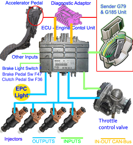
The  basic components that constitute the Electronic Power Control (EPC) circuit. 
There is no throttle cable involved, because its an electronic throttle control.
The Electronic Power Control (EPC) circuitry consists of EPC light, Accelerator Pedal, Throttle Control Valve,  DBW  (no throttle cable,) Injectors and the Engine Control Unit (ECU). Have a look at the diagram above. The inputs to the ECU is marked green and the outputs from the ECU is marked blue.  Check that the brake light bulbs are OK, if not check the brake fuses. There are other inputs to the ECU from numerous other sensors or units for example the Automatic Gearbox Control unit, Cruise control unit, Air conditioning unit, Lambda Regulation unit, Knock Sensor units, Alternator, Engine Speed Sensor unit, ABS and the  Power-assisted steering unit to mention but  a few. 

The CAN-Bus bidirectional connection is marked in orange. Some of the other inputs like Knock sensors and Lambda regulator and Engine Speed Sensor unit can also cause the EPC light to come on. If the Engine Speed Sensor unit is responsible, it will reset itself after a while and if the Lambda regulation is faulty the vehicle will smoke and turn on both MIL and EPC lights, but if the Drive-by-Wire - DBW (not drive by cable) system is faulty then only the EPC light will be on.


Both the accelerator sensors and the throttle valve sensors work on the same principle since all 4 of them are potentiometers. The input voltage is 5 Volts and the increments are in millivolts implying that there is an  acceleration range of between 0 and 5000.  Throttle valve angle  sensor 1 and Throttle valve angle sensor 2Accelerator position sensor 1 and Accelerator position sensor 2 sliders makes contact with the resistive track and outputs the appropriate voltage level to the ECU. These resistive tracks are prone to go faulty since they are gold plated contacts running on gold plated copper tracks etched on a PCB. Over time the contacts wears right through the gold and copper plating, only making contact with the bakelite or fibreglass substrate. This type of potentiometers are less reliable than ceramic thick-film potentiometers.

When the EPC warning light goes on and your acceleration goes limp and the engine won't rev-up there is an easy cure but there may be exceptions. Get the car home even if it means driving really slowly in "Limp Mode". Once home, disconnect the battery for about 15 minutes or so, but not more than 20 minutes then reconnect. NB! do not disconnect the Live terminal, disconnect the Earth terminal. If the battery is disconnected for more than 20 mins you will lose your radio settings since the radio also participates in volatile and non-volatile memory of  the CAN-Bus

Reconnect the battery but make certain that the ignition is off. Once this is done, turn on the ignition so that the dashboard lights go on but do not start your car and DO NOT touch your accelerator pedal. After about 5 minutes the throttle body will aligns itself. After 10 minutes turn off the ignition, wait for 2 mins then start the car and let it idle for abut 2 minutes as well. By now, the EPC warning light should be off and the engine will rev as normal.You may have to to this twice. If this worked for you, please do give me some feedback with a comment.


VW Airbag diagnostics 

VW Instruments - Immobilizer

   
DON'T FORGET to VISIT

VW, SEAT SKODA and AUDI OWNERS  found the following sites interesting.  
expowpphotojanicontroversy365nerdytoyslovelifelovehealthsightsofcapetownsowpboxelectroniquesblogspot-atphoto-magixgodssitesglycomix, arth-ritis, forex-bidfoodsofthecapelanguagesbarrier, pimpyocare-gimos.


COME MORE EPC DEFINITIONS

EPC - Engineering, Procurement & Contracting, 
EPC - Engineering, Plant  Construction,
EPC - European Paralympic Committee,
EPC - Electronic Product Code, 
EPC - Event Promotional Council,
EPC - Energy Performance Certificate,
EPC - Engineering, Procurement and Construction, 
EPC - Event-driven Process Chain, 
EPC - Evolved Packet Core,
EPC - European Patent Convention,
EPC - Eastern Provincial Council, 
EPC - Electronic Poetry Center, 
EPC - European Policy Centre,
EPC - European Political Community, 
EPC - European Political Cooperation, 
EPC - Evangelical Presbyterian Church 
EPC - Export Promotion Council, 
EPC - Electricity Plant Controller, 
EPC - ElectroPlating Cathode,
EPC - European Payments Council,
EPC - Electronic Packet Collision,
EPC - Electrical Professionals Council,
Etc...,