Showing posts with label ECU. Show all posts

Thursday, October 1, 2015

18020 - ENGINE CONTROL MODULE INCORRECTLY CODED

18020 - Engine Control Module Incorrectly Coded

The VW Polo 9N manufactured between 2002 and 2010 is a real fun car and is available in several formats. Meaning either Gasoline or Diesel, or hatch back GTI or sedan as in trendline, confortline or highline. Each of these  fitted with either a 1.2L, 1.4L, 1.6L, 1.8L, 1.9L or 2.0L engine. As such their Electronic Control Unit (ECU) / Electronic Diesel Controller (EDC) differs quite a bit since they are matched to their respective engines which also varies substantially. Amongst which are the ATD, AMF, AVY, AWY, AZQ, BAH, BBX, BBY, BBZ, BMD, BMS, BMT,  BNV, BNM, divided into 3 cylinder and 4 cylinder engines. These engines have  6 & 12 valves for 3 cylinder engines, and 8 and 16 valves for the 4 cylinders engines. FSI = Fuel Stratified Injection. Often times when an engine is replaced, the engine cranks but just wont start. Scanning the ECU results in a 18020 DTC - Engine Control Module Incorrectly Coded. If the engine does not originate from exactly the same model, the following list of codes aught to help to recode the ECU to the correct type.

VW Polo 9N ECU Coding

01: ECM VW Polo 9N BBY 036 906 034 DD MARELLI 4MV 4448 00031
01: ECM VW Polo 9N BKY 036 906 034 GQ MARELLI 4TV 6280 00031
01: ECM VW Polo 9N BBY 036 906 034 HL MARELLI 4MV 5511 00031
01: ECM VW Polo 9N BBY 036 906 034 DD MARELLI 4MV 4448 00071

01: ECM VW Polo 9N BKY 036 906 034 KA MARELLI 4TV G 7448 00071
01: ECM VW Polo 9N BKY 036 906 034 JC MARELLI 4TV G 6549 00031

01: ECM VW Polo 9N AMF 045 906 019 -C 1.4l R3 EDC 0200SG 1479 00000 
01: ECM VW Polo 9N BNM 045 906 019 BP 1.4l R3 EDC G000SG 8395 00002
01: ECM VW Polo 9N AMF 045 906 019 BF 1.4l R3 EDC 0000SG 5179 00005
01: ECM VW Polo 9N BNV 045 906 019 CA 1.4l R3 EDC G000SG 7537 00005
01: ECM VW Polo 9N ATD 038 906 019 JK 1.9l R4 EDC 0000SG 1558 00005
01: ECM VW Polo 9N ATD 038 906 019 LB 1.9l R4 EDC G000SG 5101 00005

01: ECM VW Polo 9N AVY 036 906 033 D 1.6l/4V SIMOS3 00HS3512 00031
01: ECM VW Polo 9N BMD 03D 906 033 F 1.2l/2V SIMOS3 00HS2509 00031
01: ECM VW Polo 9N AWY 03D 906 032 C 1.2l/2V SIMOS3 00HS2501 00031
01: ECM VW Polo 9N AZQ 03E 906 033 L 1.2l/4V SIMOS3 00HS4726 00071

01: ECM VW Polo 9N BNM 045 906 019 BP 1,4l R3 EDC G000SG 8395 00002
01: ECM VW Polo 9N BMT 03G 906 013 R4 1.9L EDC G000SG 0622 000071
01: ECM VW Polo 9N BMS 045 906 013 R3 1.4L EDC G000SG 9554 0003071

01: ECM VW Polo 9N BAH 03C 906 057 AK 1.6l BOSCH ME7.5.20 0707 0000075
01: ECM VW Polo 9N BBX 06A 906 032 PB 2.0l BOSCH ME7.5.10 0305 00071

1.2 L 3 cylinder  6valve petrol,  55 HorsePower 40 killoWatt
1.2 L 3 cylinder 12valve petrol,  65 HorsePower 47 killoWatt
1.4 L 4 cylinder 16valve petrol,  75 HorsePower 55 killoWatt
1.4 L 4 cylinder 16valve petrol,  86 HorsePower 62 killoWatt
1.4 L 4 cylinder 16valve petrol, 100 HorsePower 74 killoWatt
1.6 L 4 cylinder  8valve petrol, 101 HorsePower 74 killoWatt
2.0 L 4 cylinder  8valve petrol, 115 HorsePower 85 killoWatt

1.4 L 3 cylinder TDI,  75 HorsePower 55 killoWatt
1.9 L 4 cylinder SDI,  64 HorsePower 47 killoWatt
1.9 L 4 cylinder TDI, 100 HorsePower 74 killoWatt
1.9 L 4 cylinder TDI, 130 HorsePower 96 killoWatt

Monday, August 3, 2015

VAG FUEL TRIM PROBLEMS

SHORT TERM FUEL TRIM ISSUES

Modern day OBD-II systems can be described as high-end electronic systems that "sort of" took the automotive industry by surprise. As such , there are so many motor mechanics that have not made the transition from technologies prevalent in older model cars to the technologies pervasive in newer model cars yet, and understandably some never will.  Several of these motor mechanics don't even own a scan tool and even fewer of them are able to interpret the DTCs and the results of a diagnostic scan. With the  result, that many VW owners took it upon themselves to become ODB-II savvy and even do their own automobile repairs. Many of whom have invested in low end scan tools like VAG COM, Actron, Nextech Carmen,  Foxwell, OBD Scan, Altar, etc, and others invested in high end scan tools like G-Scan, VCDS, Xtool, Launch, AutoHex, Autel and Auto Boss etc. Even though the VW service departments are equipt with the best diagnostic scan tools they tend to lack the technical personnel with the requisite expertise to understand them and effectively repair clients VW, Audi, SEAT and SKODA cars. Electronics has taken over the modern day car and being knowledgeable about electronics is key however not every car owner  is therefore not equipt to to analyse the diagnostic printout. As an example, lets take a look at the infamous VAG fuel trim problems list below. All of them very loudly shouts that the stoichiometric  ratio is off. Generic Short Term Fuel Trim (STFT) DTCs range from P0170- P0175 which are generic government required codes and Long Term Fuel Trim (LTFT) range from P1123-P1130, P1139-P1139,  P1151-P1152, P0166-P1167 and all are manufacturer specific.

SHORT TERM FUEL TRIM (STFT)


16554 - P0170 - Fuel Trim, Bank1 Malfunction
16555 - P0171 - Fuel Trim, Bank1 System too Lean
16556 - P0172 - Fuel Trim, Bank1 System too Rich
16557 - P0173 - Fuel Trim, Bank2 Malfunction
16558 - P0174 - Fuel Trim, Bank2 System too Lean
16559 - P0175 - Fuel Trim, Bank2 System too Rich

LONG TERM FUEL TRIM (LTFT)

17531 - P1123 - Long Term Fuel Trim Add.Air, Bank1 System too Rich
17532 - P1124 - Long Term Fuel Trim Add.Air, Bank1 System too Lean
17533 - P1125 - Long Term Fuel Trim Add.Air, Bank2 System too Rich
17534 - P1126 - Long Term Fuel Trim Add.Air, Bank2 System too Lean

17535 - P1127 - Long Term Fuel Trim mult, Bank1 System too Rich
17536 - P1128 - Long Term Fuel Trim mult, Bank1 System too Lean
17537 - P1129 - Long Term Fuel Trim mult, Bank2 System too Rich
17538 - P1130 - Long Term Fuel Trim mult, Bank2 System too Lean

17544 - P1136 - Long Term Fuel Trim Add.Fuel, Bank1 System too Lean
17545 - P1137 - Long Term Fuel Trim Add.Fuel, Bank2 System too Lean
17547 - P1139 - Long Term Fuel Trim Add.Fuel, Bank2 System too Rich

17559 - P1151 - Bank1, Long Term Fuel Trim, Range 1 Leanness Lower Limit Exceeded
17560 - P1152 - Bank1, Long Term Fuel Trim, Range 2 Leanness Lower Limit Exceeded

17573 - P1165 - Bank1, Long Term Fuel Trim, Range 1 Rich Limit Exceeded
17574 - P1166 - Bank1, Long Term Fuel Trim, Range 2 Rich Limit Exceeded

17582 - P1174 - Fuel Trim, Bank 1 Different injection times

THE DEFINITION OF A BANK

Before we continue, it is important to get certain definitions right. In 8 cylinder (W8) engines and 12 cylinder (W12) engines, 4 or 6 cylinders are staggered  aligned at a V-angle,  72 degrees in relation each other, thereby making the engine more compact.  Each staggered row of either 4 or 6 cylider has its own head,  which is called a "Bank",  hence Bank 1 and Bank 2. On the other hand VR6 engines cylinders are also staggered but has a single cylinder head, however the three left most side cylinders (odd numbers) are called "Bank 1" (passenger side left-hand drive) and the right most cylinders (even numbers) are called Bank 2. Four cylinder engines normally have 4 in-line cylinders but here as well, the odd cylinders are called Bank 1 and the even cylinders Bank 2 as can be seen in the "Chassic type: Skoda Fabia  1,2l/4V" below. But this configuration does apply to all 4 and 5 cylinders engines because in some engines all cylinders are referred to as bank 1. Looking at  the above P-Codes  P0170-P0175 it can clearly be seen that  P0107 refers to Bank 1 and is common to both  P0171 and P0172. And likewise P01703 refers to Bank 2 and is common to both  P01704 and P0175. This information allows us to determine which cylinder is bank is running rich or lean. Intermittent signals may be due to continuous STFT occurrences or the bad electrical connections at the o2 sensors. However, every time the engine is started the OBD-II system  does a self test on the O2 sensors,  and should the Check engine light not remain on, then the O2 sensor is probably not the culprit.
______________________________________________________________________

Chassis Type: 6N - VW Polo
16554 - Fuel Trim: Malfunction: Bank 1
P0170 - 35-10 - - - Intermittent

Chassis Type: 6N - VW Polo
16555 - Fuel Trim; Bank 1: System Too Lean
P0171 - 35-10 - - - Intermittent

Chassis Type: 6Y - Skoda Fabia
16555 - Fuel Trim: System Too Lean: Bank 1
P0171 - 35-10 - - - Intermittent

Chassis Type: 3B - VW Passat B5
16555 - Fuel Trim: System Too Lean: Bank 1
P0171 - 35-10 - - - Intermittent

Chassis Type: 9N - VW Polo
16555 - Fuel Trim; Bank 1
P0171 - 35-10 - System Too Lean - Intermittent

Chassis Type: Audi 3.2
16556 - Fuel Trim; Bank 1
P0172 - 35-10 - System Too Rich - Intermittent

Chassic type: Skoda Fabia  1,2l/4V 
16557 - Fuel Trim: Malfunction: Bank 2
P0173 - 35-10 - - - Intermittent

Chassis Type: 6N - VW Polo
16556 - Fuel Trim; Bank 1
P0172 - 35-10 - System Too Rich - Intermittent

Chassis Type: 3B - VW Passat B5
16556 - Fuel Trim; Bank 1
P0172 - 35-10 - System Too Rich - Intermittent

Chassis Type: 1J - VW G/J/B Mk4
16556 - Fuel Trim: System Too Rich: Bank 1
P0172 - 35-10 - - - Intermittent

Chassis Type: 9N - VW Polo
16556 - Fuel Trim: System Too Rich: Bank 1
P0172 - 35-10 - - - Intermittent

Chassis Type: 6N - VW Polo 
16556 - Fuel Trim; Bank 1
 P0172 - 35-10 - System Too Rich - Intermittent

Chassis Type: 8D - Audi A4 B5
16557 - Fuel Trim; Bank 2: system too lean
P0174 - System too Lean

Chassis Type: 4F0 - Audi A6 3.2L
16559 - Fuel Trim; Bank 2
P0175 - 007 - System Too Rich

Chassis Type: 4A - Audi 100/A6 C4
16559 - Fuel Trim: System Too Rich: Bank 2
P0175 - 35-00 - -
16556 - Fuel Trim: System Too Rich: Bank 1
P0172 - 35-10 - - - Intermittent
16557 - Fuel Trim: Malfunction: Bank 2
P0173 - 35-00 - -
16554 - Fuel Trim: Malfunction: Bank 1
P0170 - 35-10 - - - Intermittent

Chassis Type: 8D - Audi A4 B5
16554 - Fuel Trim; Bank 1: Malfunction
P0170 - 92-00 - Unknown Error Elaboration
16554 - Fuel Trim, Bank 1
P0173 - 92-00 - Unknown Error Elaboration
17658 - Fuel Level too Low

Audi A4 B5 96 a4 2.8l
16558 - P0174 - Fuel Trim, Bank 2
P0174  - System too Lean  -detecting lean fuel in exhaust
16555 -  Fuel Trim, Bank 1
P0171  - System too Lean -- detecting lean fuel in exhaust
16554   Malfunction
P0170 - 35-10 - - - reached maximum amount of fuel adjustment
16557 - Fuel Trim; Bank 2
P0173 - Malfunction

Fuel Trim: System Too Rich means / Rich Mixture implying too much fuel, not sufficient air
Fuel Trim: System Too Lean means / Lean Mixture, implying too much air, not sufficient fuel

Correct combustion relies on an air/fuel mixture of 14.7 to 1 ratio. Meaning 14.7 parts air to every 1 part of fuel, but if  the air ratio dips below 14.7 parts, then the mixture is called  "rich", whereas when the air exceeds 14.7 parts, then the mixture it is called  "lean".  To keep the engine running properly, the Engine Control Module measures the oxygen content in the exhaust emissions with the oxygen (O2) sensors in the exhaust system and makes adjustments to the mixture by injecting more or less fuel. The ECU is capable of keeping the STFT air/fuel mix within  specific parameters under normal conditions, and is based on input signals  from the Barometric Pressure Sensor and the Oxygen Sensor and will make minor adjustments to the air/fuel mixture. However when these adjustments it makes exceed a internally stored predetermined level, it sets  a fault code. When DTC P0171 and P0174 are triggered, the oxygen sensors are detecting too much oxygen in the exhaust fumes instructing the ECU to add more fuel in order to maintain a correct  air/fuel mixture.  But when DTC P0172 and P0173 are triggered the reverse is implemented. When DTC P0170 and P0173 are triggered the ECU is unable to compensate for the errors and uses an internally generate signal as compensation.  The main causes of STFT DTCs are due to leaking vacuum  hoses or a poorly functioning  Mass Air Flow Sensor sensing too little air or a faulty Barometric Pressure sensor or insufficient Fuel Pump pressure. Functionality of all these sensors can be checked by verifying there scan data before attempting to replace them. Cleaning the MAF wire with electro cleaner may help but take care not to damage it. Symptoms of STFT DTC may cause the EPC light to come on, make the car go into limp mode, stall, hesitate before acceleration, idle unevenly, backfire and refuse to idle. LTFT will be dealt with in future blog.


Thursday, April 9, 2015

EPC


ELECTRONIC POWER CONTROL

EPC LIGHT

The EPC fault indicator lamp is very well known among the VAG community, and for those not yet familiar with the EPC light;   it's an  amber symbol in the instrument panel displaying the uppercase letters EPC, which is the abbreviation for Electronic Power Control. This EPC lamp is often referred to by automotive technicians as K132.  EPC is synonymous to Drive-by-Wire which means that the vehicle concerned is fitted with an electrically controlled throttle valve. Restated, the old mechanical throttle cable has now been replaced by an electronic throttle control system. Vag vehicles fitted with  Motronic Engine Management version 5.9 ECUs  and older, still use a cable operated throttle interfaced with  a Throttle Control Module (TCM) and appear to be less susceptible to EPC related problems but not immune. Whereas vag vehicles fitted with Motronic Engine Management version 7.5 coupled to a Drive-by-Wire system appear to be somewhat more susceptible to EPC related problems. This is because ECUs with MEM 7.5  was specifically designed to handle the new torque-oriented  EPC function.   

However, the  bright orange EPC fault indicator light has absolutely no effect on the functionality of the Throttle Control System as a whole. When the ignition is initially turned on, it is perfectly normal for the EPC light to come on briefly,  then switch off again, if and only if it detects no Throttle Control System DTCs in memory and also determines that the TCS is working OK.  This ECU self diagnostic test takes all of 3 seconds. But, should a problem exist, the EPC light will remain on, since it needs to inform you of a DTC stored in memory  and that any additional TCS faults won't make it glow any brighter. (NB! There is no other visual way of showing you that there are several EPC errors other than with a scan tool). 


DRIVE-BY-WIRE

The Drive-by-Wire system consists of  an accelerator pedal module, that houses  two accelerator position senders, a throttle control module that also housing two position sensors,  a throttle
valve drive servo motor, an EPC light,  an ECU and of course the wiring to connect them together. 


THROTTLE CONTROL

The two accelerator position senders are a fixed part of the accelerator pedal and in reality are potentiometers. They get their supply voltage from the ECU that is capable of component diagnostics and constantly monitors its inputs. When the ECU detects that one potentiometer signal failed, it sends a DTC to the memory and turns on the EPC light then switches to the second potentiometer. It uses the accelerator pedal input voltage and translates its position  into an output voltage that drives the throttle body servo motor that controls the butterfly valve. The two throttle two position sensors, sends feedback to the ECU. Once again theses sensors are potentiometers, also monitored by the ECU and as above, if one potentiometer fails it sends a DTC to memory, turns on the EPC light then switches to the other potentiometer, but not necessarily in that order.


WIRING

The CAN Bus wire pair for the Powertrain  are Orange/Black and Orange/ Brown but there is also a supply wire (Red) and an earth (Black) wire, to each of the Drive-by-Wire components. Each of these wires have a plug and each of these plugs have at least four wires. Do the math and you could have 8 plugs - 32 male contacts pluging into 32 female contacts. The accelerator pedal potentiometers fault finding procedure.  Any of these contacts could be intermittent, all of which will cause the  EPC warning light to light up and if any of the Drive-by-Wire components fail will do the same. Considering cars drive on bumpy roads, withstand extremes engine heat and freezing temperatures at night besides rainwater that could find its way into the wiring harness. All of which could contribute to intermittent electrical connections.


REPAIRING EPC FAULTS

Repairing EPC faults are easy but needs to be systematic, because everything that can cause the problem needs to be thoroughly investigates and exonerated before the next item is suspect. Before any major or expensive components are replaced, check the wiring. Check the wiring, Check the Wiring.  Suspect the potentiometers first since they suffer from wear and tear. 


POTENTIOMETERS

A potentiometer is essentially a potential divider. Restated, its a three legged device, with a fixed high potential (voltage) and a fixed low potential (voltage)  at two of its legs. The third leg outputs a variable potential (voltage) less than the higher potential and more than the lower potential.  A potentiometer is normally made of bakelite or fibreglass with a carbon track attached to it.  The variable output makes contact with slider that runs on this carbon track. This sider/carbon contact isn't very good because its a sprung loader pressure contact. Besides when the carbon track wears through which is just a matter of time because it is constantly at work when you accelerate. It is going to give you the EPC fault guaranteed.

Feel free to upload your VWSKODASEAT & AUDI scans.

Friday, March 20, 2015

AUDI EPC LIGHT

AUDI HAS LOOMINITUS

Audi TT, A4 1.8T, A4 B5 1.8 Auto, 2.5 V6 Quattro B6, 1.6L A4 SE, 1.8L R4, Audi 8T0, Audi A6 C5,

Does your Audi occasionally have a hard time starting, yet finally starts just before you give up?  So when it starts, the EPC and ESP lights are on, then the engine cuts out. You restart and she idles rough and the check engine light comes on? After a while the EPC and ESP light go out, thereafter the car drives normal until the next time this happens. 

Or, as you are driving in manual mode, you noticed the ABS and ESP lights come on and suddenly your Audi's engine loses  power and goes into limp mode. You switch off, then restart, it idles rough but won't rev over 1500 RPM and she sounds like a tractor. You switch off once again, restart and the tractor is gone. So you get the Audi home driving at a snails pace, the next morning you start her and it seems like there was never any problems because she now idles and drives normally.

Or you are VCDS savvy, encountered an EPC light problem, cleared the fault and the next day it come back on. Several days later the EPC light comes on again, stays on and refuses to switch off. Once again you do a scan and you get a ton of  implausible  and intermittent DTC errors. 

Or your start the Audi, it idles for a few seconds then dies with the EPC light and ESP lights on. You clear the faults, lights go out. You drive the car for less than 3 km and it goes into limp mode. You disconnect the battery and reconnect and it seems fine thereafter. A few days later and the same thing occurs.


The Throttle body plug thats seem to haunt Audi owners.
What you have been experiencing is just a sampling of what the future holds. You Audi is suffering from "loominitus",  its loom is having issues, better known to auto electricians and motor mechanics as wiring harness issues. The culprit in all the above case is the 6 pin plug interfacing with the throttle body. Of late, this throttle body plug has become  quite trouble, you could almost call it common. Don't use contact spray on the plug. Ideally that portion of the loom needs to be replaced but since the female part of the plug is intermittent - hence faults come and go - it's worthwhile just replacing the plug and join the wires using ferrules and double crimp them. Cover the wires with shrink sleeving and avoid insulation tape because the engine heat will melt the PVC which will go sticky within days and  its messy.  

The troublesome Throttle body plug - connect thicker wires as per old plug.
Pin 1-blue/white stripe, Pin  2-purple/white stripe, Pin  3-white, Pin  4-blue/grey stripe, Pin  5-purple/black stripe, Pin  6-white/grey stripe
Throttle body replacement plug and colour coded wiring

I am so sorry to say, 
as the looms in the newer cars age, you should expect worse issues with the wiring harnesses.  See the list of sub loom components for the VW Polo here. Pieces of the harness that makes-up the whole.

Anyway should you scan your ECU, you will most probably find the following faults and perhaps others not listed here. The image below points to the troublesome plug.

18010 - Power Supply Terminal 30: Voltage too Low
P1602 - 35-10 - - - Intermittent
01314 - Engine Control Module
013 - Check DTC Memory - Intermittent
18084 - EPC Warning Lamp (K132) Circuit
P1676 - 35-00 - Electrical Malfunction
01176 - Key
65-10 - Unauthorized - Intermittent
01177 - Engine Control Unit
64-10 - Not Currently Testable - Intermittent
01119 - Gear Recognition Signal
             35-10 - - - Intermittent
18264 - Throttle Potentiometer (G69): Error Message from ECU
             P1856 - 35-10 - - - Intermittent
00258 - Mass Air Flow Sensor (G70)
              P0102 - 002 - Signal too Low - Intermittent
18039 - Accelerator Position Sensor (G79)
P1631 - 35-00 - Signal too High
18042 - Accelerator Position Sensor 2 (G185)
P1634 - 35-00 - Signal too High
00768 - Random/Multiple Cylinder Misfire Detected
              P0300 - 35-00 - -
16685 - Cylinder 1: Misfire Detected
             P0301 - 35-00 - -
16688 - Cylinder 4: Misfire Detected
              P0304 - 35-00 - -
16690 - Cylinder 6: Misfire Detected
              P0306 - 35-00 - -
16689 - Cylinder 5: Misfire Detected
             P0305 - 35- 00 - -
17953 - Throttle Valve Controller
P1545 - 35-10 - Malfunction - Intermittent
17981 - Left Engine Mount Solenoid Valve (N144)
              P1573 - 009 - Open Circuit
00473 - Control Module for Elect. Park/Hand Brake (J540)
              008 - Implausible Signal - Intermittent
01494 - Bulb for Parking Lamps; Left (M1)
             011 - Open Circuit
01504 - Bulb for License-Plate Light (X)
              009 - Open or Short to Ground - Intermittent
02255 - Voltage Measuring Lead from Vbat
             009 - Open or Short to Ground
16706 - Engine Speed Sensor (G28): No Signal
             P0322 - 35-00 -  -
00285 - ABS Wheel Speed Sensor; Front Right (G45)
008 - Implausible Signal - Intermittent
00283 - ABS Wheel Speed Sensor; Front Left (G47)
012 - Electrical Fault in Circuit - Intermittent
18057 - Powertrain Data Bus: Missing Message from ABS Controller
P1649 - 35-10 - - - Intermittent
16795 - Secondary Air Injection System: Incorrect Flow Detected
P0411 - 35-10 - - - Intermittent
17511 - Oxygen (Lambda) Sensor Heating; B1 S1: Performance too Low
P1103 - 35-10 - - - Intermittent
16497 - Intake Air Temp. Sensor (G42): Signal too High
P0113 - 35-10 - - - Intermittent
16955 - Brake Switch (F): Implausible Signal
P0571 - 35-00 - -


Audi on a rollback, notice the open bonnet

Audi on a rollback, number plate scratched for privacy

Audi on a rollback just before  peak hour in the afternoon.

Audi on a rollback enroute the service centre.
Audi on a rollback  

Audi TT, A4 1.8T, A4 B5 1.8 Auto, 2.5 V6 Quattro B6, 1.6L A4 SE, 1.8L R4, audi 8T0, Audi A6 C5,

Feel free to upload your VW, SKODA, SEAT & AUDI scans.

Tuesday, October 21, 2014

EPC DEMYSTIFIED CONTINUED 2


Continued from EPC DEMYSTIFIED CONTINUED 1.


  ...  I only became aware of this when my EPC light went on due to the knock sensor. See picture blog.  More...


 PART 3


BREAKING THE CODE

What needs to be mentioned as a basis of understanding, is that OBD (on-Board Diagnostics) was introduced in the 70's along with CDI (capacitive discharge ignition systems) as DIY kits. Few cars had fuel injectors, points and coils were fast being taken over by electronic modules. During this time some standards were introduced but they were not very well defined and as such manufacturers developed their own and applied their specific systems and developed their own code descriptions which later became known as OBD1. This was considered undesirable and counterproductive since none franchised service, and general mechanical repair centers had to purchase different scan tools, interface cables and connectors, skills and manuals for each make and model of car they specialized in. This resulted in vehicle diagnostics becoming unwieldy expensive. In February of 1986, Robert Bosch founder of Bosch, introduced the CAN (Controller Area Network) serial bus system to  the Society of Automotive  Engineers (SAE) in motor town of Detroit.

This influenced the  Society of Automotive  Engineers (SAE) who subsequently drafted a list of standards and practices that aught to be implemented by all automobile  manufacturers and recommended them to the Environmental Protection Agency (EPA). The EPA weighed-up these standards and recommendations, acknowledged their benefits, and adopted them. The standards criteria included a precisely defined diagnostic connector for each auto manufacturer, a standard scan tool and a common electrical communications protocol and a common data format, and the ability to monitor other
vehicle parameters. Lastly that the standard scan tool should interface with vehicles of all manufacturer. It also included mandatory definitions and descriptions for certain emission control system  defects which was labeled the ‘P0’ Codes. Manufacturers were allowed to generate and use their own ‘manufacturer specific code descriptions’ known as ‘P1’ Codes. This collaboration of standards became known as OBDII, (OBD2) and was adopted for implementation by January of 1996. Two types of scanner codes, namely manufacturers codes like VAG codes and SEA Codes are now the standard practice.

OBD-II  

As mentioned above, Powertrain Control Module (PCM) error codes are assigned the prefix P and pertain to the, Engine management, Transmission management, Fuel Pump and Gasoline Management, Automatic Transmission – Hydraulic Control, Emission control system, evaporative emission purge control (HVAC), Auxiliary module management and other some 0n-board Hybrid application.  For example P1340  suggests that the Powertrain triggered a DTC and describes it as an "Crankshaft-/Camshaft Position Sensor Signals Out of Sequence"

From the above example it would thus be easy to interpret the DTC below relating to EPC (Electronic Power Control)

DTC (VAG)   DTC (SAE)  Society of Automotive  Engineers

16504 P0120 Throttle Position Sensor A - Circuit Malfunction
16505 P0121 Throttle Position Sensor A - Circuit - Performance Problem - Out of Range
16506 P0122 Throttle Position Sensor A Circuit - Low Voltage Input
16507 P0123 Throttle Position Sensor A Circuit - High Voltage Input
16894 P0510 Throttle Position Sensor - Closed Switch- idle micro-switches -F60 malfunctioning
17951 P1543 Throttle Actuation Potentiometer - Signal too Low
17952 P1544 Throttle Actuation Potentiometer - Signal too High
17913 P1505 Throttle idle micro-switches -F60 not/short-circuit opens
17914 P1506 Throttle idle micro-switches - Switch Does Not Open/Short to Ground
17988 P1580 Throttle Actuator (B1) Fault - May be caused by low battery if found with 16487 (P0103)

18038 P1630 Accelerator Pedal Position -G79 signal too small  (low)
18039 P1631 Accelerator Pedal Position -G79 signal too largely (high)
18040 P1632 Accelerator Pedal Position -G79 supply voltage malfunction
18041 P1633 Accelerator Pedal Position -G185 signal too small
18042 P1634 Accelerator Pedal Position -G185 signal too largely
18047 P1639 Accelerator Pedal Position 1+2 Range/Performance -G79 and -G185 implausible signal
18048 P1640 Internal Controller Module defective (EEPROM) Error

EPC Circuit.

The 
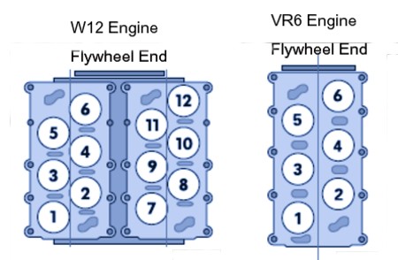
EPC  circuit consists of a number of disparate components that control and supervise, regulate and determine the throttle valve position at all times. They include;

1) the accelerator pedal position sender (TP sensor G69)
2) the accelerator pedal position sender -2, (G185)
3) Black 6-pin plug with 6-pin with Gold plated contacts

NB! The above three components are part of the accelerator pedal.

4) the throttle valve control module (unit),
5) the K132 EPC fault lamp, (electronic throttle control fault indicator)
6) the engine control module (unit).

Firstly we going to do a test on components 1, 2 and 3 above. To do this test, you need a Fluke multimeter or similar for a voltage and continuity / resistance test. Unplug the 6-pin plug from the accelerator pedal and switch on the ignition. Connect the multimeter and check for a 4.5 volt reading between;-

pin 1 and ground, then between pin 1 and pin 5
Pin 2 and ground, then between pin 2 and 3.
If tests prove to be "OK", switch ignition off.
Do additional checks for short circuits between one another and ground and if this checks "OK",

Locate the ECU, normally inside cowl. Disconnect the ECU from its socket, identify pins 34 & 34, 35 & 36, and 72 & 73 on the socket. Disconnect the 6-pin plug from the accelerator pedal once again and check for continuity between this plug and the ECU socket. There should be continuity between pins:-

1 of the 6-pin plug and pin 72 of the ECU socket.
2 of the 6-pin plug and pin 73 of the ECU socket.
3 of the 6-pin plug and pin 36 of the ECU socket.
4 of the 6-pin plug and pin 35 of the ECU socket.
5 of the 6-pin plug and pin 33 of the ECU socket.
6 of the 6-pin plug and pin 34 of the ECU socket.

Any resistance above 1.5ohms should be investigated for corrosion. This often causes the engine to surge (idle unevenly or rather breaths) However, if this test proves "OK" and no wiring malfunction is detected, replace G69 and G185 (single unit) on the accelerator pedal. NB! these components are non adjustable and needs to be replaced as a whole.

When the ignition is turned on, the ECU checks all EPC components necessary for the proper  functioning of the Electronic Power Control. If a malfunction is detected in the EPC (Electronic Power Control) system whilst the engine is running, the ECM will simultaneously activate the EPC (Electronic Power Control) warning light and make an entry of this malfunction in  the ECU (electronic Control unit) DTC (Diagnostic Trouble Codes non-volatile memory.  By a process of eliminate the EPC fault can be fixed.

The list below categorises VW and Audi manufacturer predetermined data groups which varies depending on the vehicle, year, engine, engine code and management system on board.

Group Number / Group Category

1–9     General engine activity data
10–19 Ignition data
20–29 Knock control data
30–39 02 sensor control system data
40–49 Three-way CAT data
50–59 Engine speed control data
60–69 Throttle drive data
70–79 Emissions reduction data
80–89 Special function data
90–97 Power increase data
98–100 Compatibility data
101–109 Fuel Ignition data
110–119 Boost pressure control data
120–129 Control unit communication data
130–150 Special info data

Based on the data from the above table EPC problems are associated with group 60-69. However, on Expert Systems Diagnostics Group 60, holds the EPC Adaptation data, group 61 holds EPC-system 1 data and group 62 holds the EPC system 2 data. Group 66 holds the speed-o-cruise data.

NB! If you found this information useful, please link to this page.

Wednesday, May 15, 2013

Volkswagen Electronics


VOLKSWAGEN ELECTRONICS

AUDI  MODULE CODING

Electronics has taken over the modern day car, a trend that started prior to 1994. Since then  motor vehicle electronics technology has taken on a completely different form. With the advent of OBD (On-Board Diagnostics) there has been strides to standardize automotive electronics in all vehicles with relative success. With the arrival OBD II automotive electronics standardization was close to uniform, however there were other derivatives, among which was EOBD (European OBD). Thereafter, CAN-Bus was introduced which is now the defacto standard for all cars built after 2008 internationally. All cars built from 2012 only sports CAN-Bus,  and are not backward compatible to older ODB II protocols, like KWP2000 for example. This move implies every auto technicians who financially invested in ODB II scanners will have to get the latest equipment in order to scan the latest cars. Just look at the Audi Q7 with its 50+ electronic modules all of which are CAN-Bus only. 
Audi Q7 has more than 50 Electronic Modules.

The hexadecimal list of Electronic Modules below are just an idea of what can be expected in current and future motor vehicles many of them having as many as 24 different module versions, many modules are incompatible with the various models of Audi, VW, Skoda and SEAT, each with its own features and coding.

02: Auto Trans
05: Acc/Start Authorization
07: Control Head
08: HVAC
0E: Media Player 1
0F: Digital Radio
11: Engine II
13: Auto Dist. Regulation
15: Airbags
16: Steering Wheel
18: Aux. Heater  
19: CAN Gateway
1E: Media Player 2  
20: High beam assist
22: All Wheel Drive
28: Heating / Air Conditioning (Rear)
2E: Media Player 3
34: Level Control
36: Driver's Seat
3C: Lane Change
3D: Special Function
42: Door Elect, Driver
47: Sound System
4F: Centr. Electr. II
52: Door Elect, Pass
55: Headlight Range
56: Radio
57: TV Tuner
5C: Lane Maintenance
61: Battery Regul.
62: Door, Left Rear
65: Tire Pressure Monitor
67: Voice Control
6C: Back-Up Camera
6D: Trunk Electronics
72: Door, Right Rear
77: Telephone


AUDI : - SOME ENGINE CONTROL UNITS AND CODINGS


Engine:

Controller:     8E0 909 518 A,
Coding:         0011581 or 0016711

Controller:    8E0 909 518 AA

Coding:         0011501

Controller:    8E0 909 518 AC
Coding:        0004501 / 0004581

Controller:     8E0 909 518 AF
Coding:         0016701 / 0016751 / 0016581

Controller:     8E0 909 518 AK
Coding:         0016711 /  0016751 /  0016501

Controller:     8E0 909 518 AL
Coding:         0011584

Controller:     8E0 909 518 AS
Coding:         0011511

Controller:    8E0 909 518 AQ  
Coding:        0011501

Controller:     8E0 909 518 F
Coding:         0016701 or 0016751

Controller:     8E0 909 518 G
Coding:         0016581


 AUDI Automatic Transmission 
codings will be covered in Future Blogs.

VIN Number identification 
will also be covered in Future Blogs.

Volkswagen’s new modular architecture 
will also be covered in Future Blogs.


Friday, May 10, 2013

VW ABS CODING


VOLKSWAGEN ABS DIAGNOSTICS

Using a code reader or  diagnostic tester to view your VW Polo ECU data is quite a treat and is also really cool. A view of the data just exudes the growth of motor vehicle technology in general and it is quite humbling if you are electronically minded and quite intimidating if you are mechanically minded.  However there is often the temptation to change a number or something, just to see what happens to your Volkswagen. If you are one of those people who just did that, I bet you have a wistful regret, wishing that you never did so in the first place because you got yourself a "01044 control module incorrectly coded error." Or perhaps you  swapped a 1996 VR6 engine into a 2007 MkV GTI chassis and got a "01044 control module incorrectly coded error." Or you had your car serviced and the ABS and ESP light stays on in the instrument panel and showing up as a "01044 control module incorrectly coded error."  Or you cleared that nagging airbag light on your VW Beetle, only to get a "01044 control module incorrectly coded error."

Control modules codings are normally NOT interchangeable since virtually every model among the numerous versions of  VW's  each have a different ABS/ESP modulePower Assisted Steerin Module, Climate control ModuleInstrument Module, Immobilizer Module and Engine Control Module and so many other modules. Taking this into consideration,  it is more than  obvious that one should NEVER copy coding from a different model VW, AUDI, SKODA or SEAT and paste it into your own VolkswagenAUDI, SKODA or SEAT, unless you write down your original modules original coding so that you can revert back to it later, should things appear to go pear shaped. 

However if the two VW, AUDI, SKODA, or SEAT are the same in every respect, then  their module codings will be identical and therefore perfectly fine to use. Be particular about the module suffix since different suffixes signify different software versions which may not be compatible to your VAG car. Virtually each module that appears identical but has different letter suffixes will invariable have a different coding. So the rule is same car, same module, same module number, same module suffice, same coding. Disregarding this could incapacitate your car and cost you a huge amount of money.

Every Control module coding is stored as an onboard binary number, which in essence is the binary sum of the features for that specific module. Whereas the ECU also stores an onboard binary number which is the binary sum of all the Control Modules fitted in the car. This binary sum is called the checksum and any incorrectly coded  module will result in an erroneous checksum. If this is the case, the erroneous checksum is compared to a reference checksum also stored in the ECU module and any discrepancy could incapacitate your Volkswagen completely or present you with some peculiarities and error codes to match. Like the notorius 01044 control module incorrectly coded Checksum verification was adopted by BOSCH Motronic ECUs to validate its EPROM's stored data. Having said that, it is wise not to change the coding or replace any control modules in your VW AUDI, SKODA or SEAT unless you are au fait with binary and hexadecimal number systems

Below, is a list of VW ABS controllers and their respective coding which vary from  'ABS FRONT MK60 0101' to  'ABS 8.0 front H03 0002' to 'ABS 8.0 front H05 0002' to 'ABS 5.7 FRONT V20' to 'ABS 5.7 FRONT V30 ' to 'ABS/ASR 5.7 FRONT V20' to 'ABS 5.7 FRONT V00' to 'ESP 8.0 front H03 0001' to 'MABS 8.0 front  H04 0002' to 'ESP 8.0 front H03 0001' to 'ABS 8.0 front H03 0002' to mention but a few. Several VW, AUDI, SKODA and SEAT owners and mechanics are constantly searching the Internet for ABS module coding and hopefully this information may help them to get their Volkswagens, Skodas, Seats,  Audis and other VAG cars up and running once again.

VW POLO 6Q0 907 379 AC ABS Pump

VW Polo 9N
Address 03: ABS Brakes
Controller: 6Q0 907 379 AC
Component: ABS 8.0 front H03 0002
Coding: 0000145

ALTERNATIVE ABS MODULE CODING
NB! These are the codings I currently have but are certainly not the only ones use by Volkswagen, SEAT, Skoda and Audi. As I get them I will update this list.

6Q0 907 379    - Coding:  00036 or 00044
6Q0 907 379 AA - Coding: 0000005 or 0000008
6Q0 907 379 AB - Coding: 0000005 or 0000008
6Q0 907 379 AC - Coding: 0000145 or 0000142

6Q0 907 379 AF - Coding: 0002061 or 0002079 or 0002082 or 0002085 or 0002103 or 0002115 or 0002118 or 0002122 or 0002136 or 0002145 or 0002175 or 0002181 or 0002190 or 0002193 or 0002199 or 0002202
As can be seen above, AF suffix has the whole gamut of codings and each should be tried before throwing in the towel.

6Q0 907 379 AG - Coding: 0002202 or 0002229 or 0002238
6Q0 907 379 AH - Coding: 0000299 or 0000284
6Q0 907 379 AQ - Coding: 0002356
6Q0 907 379 AS - Coding: 0002347 or 0002368 or 0002368 or 0002491
6Q0 907 379 AT - Coding: 0000269
6Q0 907 379 BC - Coding: 0002136 or 0002098
6Q0 907 379 C  - Coding: 00044
6Q0 907 379 D  - Coding: 00124 or 00188
6Q0 907 379 E  - Coding: 0001097
6Q0 907 379 G  - Coding: 00044 or 00045
6Q0 907 379 H  - Coding: 00188
6Q0 907 379 L  - Coding: 0001097
6Q0 907 379 M  - Coding: 0000000
6Q0 907 379 R  - Coding: 0000008
6Q0 907 379 T  - Coding: 0000281 or 0000296 or 0000299

Make some quick money
Eat as much as you like at Alfonso's Wedding
A Classic Wedding Cake